Cool Air Induction
Years ago I tested the temperature at the inlet of my modified stock 89 airbox.
I had disconnected the air tube from the computer to the airbox, and I had
enlarged the opening of the airbox. It was sucking in warmer under-hood air that
way, but most of that extra heat was being pulled away by the intercooler, so I
didn't really care.
Nevertheless I
wanted to see what the temp of the air was at the inlet as a base reference for
future mods. On a 60^ day I took a 7 mile cruise, and at the end of it I
recorded 88^ at the inlet, for a 28^ rise over ambient. The temp sensor was
right up against the pleats of the K&N air filter.
Later that week I
recorded "cruise" temps again. It was a 52^ day, and I recorded 80^ at
cruise. I usually cruise with the cruise control set at 75 mph when I'm testing
stuff. I saw 28^ over ambient at cruise once again.
Very recently I
moved my intake to the left front space where my battery used to reside. This
space is the recipient of a small round cool air inlet that originally had a
tube on it running into the computer (to feed it air). The computer tube is long
gone, the long computer inlet has been hacksawed off the computer, and cool air
*theoretically* shoots into the "ex-battery-area" where I've placed my K&N
cylindrical filter. I tested again, but this time I tested temps right in
between the pleats of my relocated K&N, on the side facing the cool air
hole, and on the side facing away from it. The filter is laying down where the
stock battery used to be.
I cruised for 7
miles, and on the "cool side" of the cylindrical filter I recorded 2^ over
ambient! Outstanding! I moved the temp sensor to the "warm side" of the K&N,
and cruised home again... 5^ over ambient! This means that air in the filter is
in the vicinity of 3.5^ above ambient, which is *far* better than I had hoped
for. I didn't expect to see a big difference like that until I had sealed off
the area with little walls under the hood. ...Which is great, because I didn't
plan to make the little walls at all; I was moving the filter just to keep
puddles from spraying water into it!. I've never experienced hydraulic lock up,
and I don't want to start now!
I truly didn't
expect to see a 20^+ temp drop from an un-sealed filter just sitting in the open
where the battery used to be. Surprise! The only mod to that open area is
cutting off a corner of the un-used battery tray, and drilling about 10 little
3/8" holes in the fender right near the inlet of the computer (under the
filter).
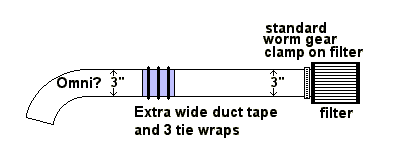
Here's how I made a quick and easy low-buck 3" intake: I got the intake tube from an older 2.2 T1 car, maybe an Omni; I can't remember. The old style T1 intake tube is much larger internally than the newer 2.5 T1 intake tube. I mounted the larger intake tube over the same spacer ring that my K&N mounted onto at the turbo inlet. Same spacer, same clamp... sweet. I went to Home Depot and bought 8 feet of 3" aluminum flexible duct tubing for about $5. It will do 2 cars. I slid the end of the old T1 tube right into the metal tubing, and then put a ring of extra wide duct tape over the joint. I then used 3 tie wraps to REALLY hold the tape there forever. The other end of the metal tubing slips *right* over the K&N's inlet! A regular worm gear clamp holds it there.
I'm not a fancy-parts worshipper, and had no intention of considering looks at all, but after all is said and done it actually looks fine.
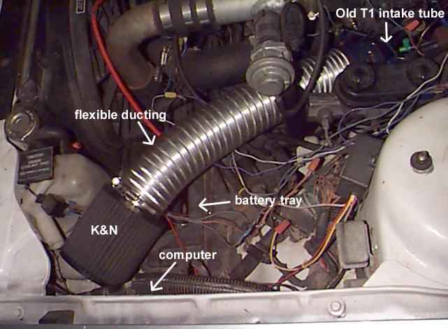
If you haven't moved over your battery the space will be
much tighter, but that aluminum ducting is VERY flexible, and does easy 90^
bends to go around things. You should be able to find a cooler spot than on the
turbo inlet, where it seems to be 28^ above ambient at cruise (75 mph).
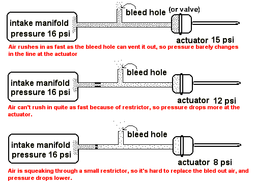
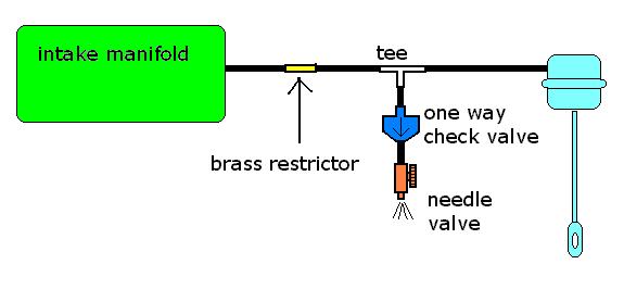
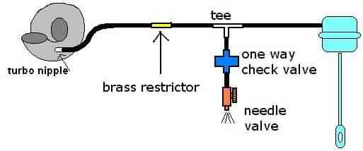
In the above illustration air molecules represented by dots are leaving the intake manifold and heading for the actuator. Just as you can make the actuator "see" less pressure than you're really running, you can also make the MAP sensor see less pressure than you're running. Same deal with the MAP line; orifice goes between the pressure source and the bleed hole/valve. Now you know why.
EXHAUST
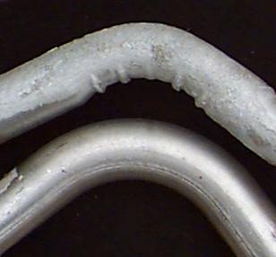
Mandrel bent pipes are said to flow 35% more than crimp (or "regular" bends. Take a look below at two 3" pipes. Do you have any reason to doubt it??
INTAKE
Extra clamps can aid flow, when placed properly.
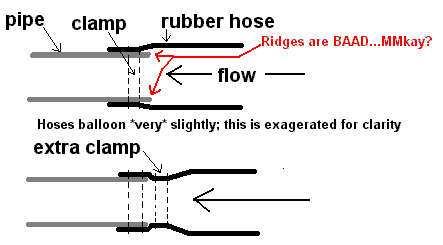
The hoses balloon just a little under high boost, but even
when there's low boost present, you still have the pipe edges hampering
flow.
The second clamp creates a smoother
transition from rubber hose to metal tubing. I don't bother to use them when the
flow is going the other way...
To make your own intercooler tubing, see: intercooler
tubing
ENGINE
Reading Spark Plugs: Mild detonation, that you might not hear, is evidenced by small
"salt & pepper" specks on the center electrode insulator. (white porcelain)
They're tiny specks; the light ones ("salt") are tiny molten droplets of
aluminum that have hit your insulator, then cooled off and hardened on it. The
dark specks ("pepper") are carbon specks that have been blasted off of the
cylinder head and piston top.
Another
common bad sign is a slight rounding of the edges of the plug's electrodes. The
corners of the electrodes should be sharp 90 degree angles, not rounded. This is
actually a sign of leaning out, but leaning out leads to detonation. If your
plugs are OLD, this is normal. But if you put in fresh plugs, and a few passes
later they're slightly rounded at some corners, you're too lean.
These signs beg for more fuel, and/or less timing
advance, and/or less boost.
Ever wonder how
even your fuel distribution is, but can't tell by the white center insulators,
because of today's unleaded gas? Just throw a little 104+ octane booster in your
tank and drive around for a while. You will then have a reddish residue on your
plugs. The reddest ones are getting the most fuel. The whitest ones are the
leanest cylinders.
Downdraft Tube (PCV vent): The stock pvc setup sends a lot of
dirty oil to your air filter. And if you put a cone filter on your turbo,
there's no more airbox to run it into.
Put
a .75" ID radiator hose or fat garden hose onto the PVC outlet's metal tube
(coming out of the valve cover). Clamp it on *loosely*. Run the hose down to
near the road. Cut it to the proper length. Now remove it again to modify
it.
About 5 " from the bottom of the hose,
put 2 skinny nails through the hose, criss-crossed, so that they form an X
through the hose. Bend the ends over, so that they can't come out. Buy a
stainless steel scouring pad for pots & pans. Take a SMALL amount of SS pad,
and pack it LOOSELY in the bottom of the hose. Then 2" from the bottom, make
another nail cross to stop the SS pad from moving up or down the tube.
Now clamp the whole tube on tightly.
The SS mesh will pick up oil vapors, and get damp
with oil in no time. Then it acts as a filter, preventing nasty road stuff from
getting sucked up the tube when it's in vacuum. I split mine open lengthwise
after one year of use, and it was clean above the SS mesh.
Ignition: You will hear people say
that you need a super ignition to run high boost. Well, then, the stock
ignition is super; I've run 27+ psi on hundreds of races with no trouble.
Get good low impedence wires. I like the spiral-core wires; I've used several
different brands from expensive to cheap, and they all work well. Move the coil
close to the distributer so that the coil wire can be shortened to a foot or
less. Keep the wires from touching each other. Use colder plugs than
stock. Gap the plugs at .032".
If you
experience misfire at high boost (over 20 psi) gap them at .030".
If you experience misfire at low boost (under 20
psi) something is wrong with your stock set-up. Investigate your cap,
rotor, etc.
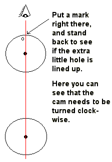
Cam Timing
I'm using the
"line of sight" method. I put a socket wrench on the cam sprocket and rotate it
until the little extra hole in it is pointing up, and then get the timing mark
to sit on "0" degrees. I stick a LONG socket on the crank pulley's center bolt
and let it stay there on it's own, sticking out sideways.
Then I look
straight down from above the cam pulley, and close one eye. I move my head until
the
center of the cam sprocket bolt is lined up
with the long socket. If the little extra hole in the cam pulley is right in
line with the cam pulley
bolt and the crank bolt,
it's OK. If it's NOT lined up, you have to remove the belt and rotate the cam
pulley in the direction that will
line it
up.
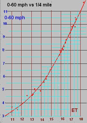
Note that each light line is worth .33 seconds as you
go from left to right, but each light line is only worh .25 seconds when you go
up or down!
Here's a Wide Open Throttle Switch that's just a cheap
"on-off" microswitch. Even Radio Shack has them. This little switch allows you
to switch from low to high boost automatically whenever you floor your car. It
can turn on a relay to activate a booster fuel pump, or anything that you want
on only when at WOT. 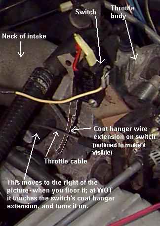
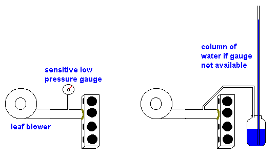
Here is some information that I derived on the homemade
flow bench. I used the electric leaf blower on the same speed, and same
voltage, on every test. I did the tests more than once to establish
repeatability. The backpressure readings are in inches of WATER, not
inches of MERCURY, nor PSI. An inch of water is roughly 1/13 of an inch of
mercury, so the gauge is 13 times more sensitive to backpressure than a mercury
gauge can be.
I used a short straight piece
of exhaust pipe as a baseline for comparison. Since 2.5" exhausts seem to
be extremely popular on turbo cars, I used 2.5" diameter pipe. I shrunk
the large leaf blower nozzle down to 2.5" at the outlet, and stuck on the
following:
2.5" short straight pipe = 2" backpressure
stock Omni glht muffler = 9"backpressure (7" more
than straight pipe)
stock Omni glht cat =
9.5" backpressure (7.5" more than straight pipe)
stock 89 Acclaim cat (shorter than Omni)= 8" backpressure
(6" more than straight pipe)
Products For
Power cat ($59.99) = 5" backpress. (3" more than straight pipe)
As you can see, the
stock Omni cat produced 7.5" more backpressure than the straight pipe, while the
hi-flo cat produced only 3" more backpressure than the straight pipe. Less than
half the back-pressure!
This is useful for anybody running a stock or Bosch BOV, or any BOV made of plastic. If you leave the factory's quick release valve in place, the stock BOV will lift off of it's seat and leak at 15 psi; the Bosch will lift off at 9 psi. If you leave the quick release valve out of the BOV line, the full boost pressure will eventually rupture the plastic housing and/or the rubber diaphragm. The pneumatic circuit below will send *part* of the boost to the BOV, but will still send full vacuum to it for a fast opening valve. Now your stock BOV will be good for over 20 psi.
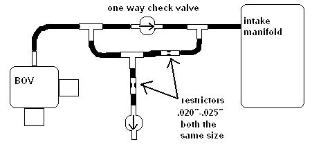
Here's the diagram for a simple manual
bleed. For a more complex and versatile setup visit Dempsey's Pages
. The setups you'll see there can be fed off of the
intake manifold, or off of the turbo's compressor nipple, if you have one on
your compressor. When hooked to the compressor outlet, high vacuum will not be
flexing the diaphragm backwards; it might help the unit to live longer.
To see what
the check valves and stuff look like in real life, visit Dempsey's general
instruction Page . There are many
variations, but look for something similar to what the photos show.
For the
latest & greatest boost controller, go to: Super Boost
Controller
Here's a simple way to stiffen a worn or weak bobble strut to keep the engine steadier under heavy loads. Common worm gear clamps hold on a split-down-the-middle iron tube. Mine's holding up great.
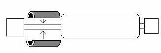
I measured the
extension of the strut at rest (the length of the shiny rod) and then cut a
thick little metal tube to about 1/4" *longer* than the measured extension. I
then took the strut off, split the tube lengthwise, and clamped it on the strut
extension. This made it necessary to jack up the rear of the tranny a little to
get the strut back on. Now my tranny is "pre-loaded", and is much more
stable.
Drawback? Yes,
vibrations only during clutch engagement. Otherwise, no vibrations are
felt while driving around.
Gain? Yes, I went
from severe wheel hop on street tires, when popping the clutch out, to no hop.
(with a pair of long smooth black marks left on the road) At the track, on
sticky tires, the wheel hop went from severe (10 on a scale of 1-10) to
mild (3 on a scale of 1-10).
Shimming the driver's side swaybar will put more weight on the light passenger's side wheel, and help spin-free launches. Only one spacer nut (oversized nut that's the thickness of the wood you're using) is shown, but you really use two; one on each side. That keeps the rubber bushing from being over squashed.