Boost
Controller
Updated May
14, 2002
Here is a boost controller that
incorporates quick spool up, minimal spikes, and minimal hassle. You will
merely have to clean it once in a while, or else put a tiny filter in front of it so
that dirt never reaches it. Then set it, and forget it.
"Grainger valve" is just a nick-name for a simple ball & spring check valve with
adjustable spring tension. McMaster-Carr sells them as part number:
48935K25
The above
set up is adjustable and you will get to see if you like the quick spool up. If
you do like it then you should add the simple parts below to make a 2-stage
controller. Then you go from one boost level to another with the flip of a toggle
switch.
You can follow the diagram below to have the quick
spool up, *ONLY* when you floor it. Sometimes "lazy" driving is required, and you don't want quick
spool up. A wide-open-throttle switch is even better than a toggle switch; you
only go to high boost when you floor it. It makes the "drivability" of the car
excellent! Try it; you'll like it! The Grainger valve controls the high boost
setting, while the "low" setting is permanently at minimum boost, which is
usually about 7 psi.
Please note
that the unused vacuum barb on the solenoid valve is
blocked off! I represented the block with a black rectangle.
You must cap off this nipple. Again, there is a small (about .020") vent hole drilled into
the output barb of the Grainger valve to act as a vent.
Because of several requests, below
you will see a fully manual "high-low" boost setup with adjustable "high", and
adjustable "low" settings. The bleed to adjust "low" acts as the vent.
If you're gonna run around with the low setting closed
a lot, then add a vent anyway! The
Grainger
valve controls the "high" setting.
Not all
solenoids flow the same. Some flow much more than others. Apply 12Vto one at a
time, and blow through them with your mouth. Use the ones that are easiest to blow through.
Solenoid valves cannot hold back high pressure that exceeds their
spring power; at some point pressure will leak past the closed valve. Get a
Mityvac and apply pressure to the center barb while12V is applied to it. Since
you have capped off the top barb, it shouldn't let any air through, and it should
hold a pressure equal to your highest boost setting. If you want to run 18 psi
boost, but the barb leaks at 12psi (for example), then pressure-test the OTHER
bottom barb, and whichever one holds MORE pressure is the one you want to face
the yellow restrictor in the diagram.
Here's how you make and adjust
it:
To
make the valve, move
the check ball to the other side of the spring.
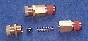
Take it from here, and put it
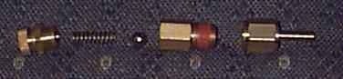
THERE! Then screw on a brass barb
fitting.(McMaster Carr part number) 5346K51
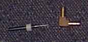
Drill a tiny hole (about .020") in a brass barb first...
(90degree brass barb is part # 44555k142)
Take a bigger
stronger bit, like a .035" or .040"bit, and slip it all the way down your chuck
until it barely protrudes. Adjust it so that it's *almost*
long enough to go all the way through the brass, but not quite.
Drill with the larger bit until it bottoms out against the chuck. Now you
have
a thin brass wall left that's easy to drill
through with the little .020" bit.
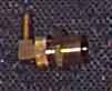
Then bang the barb into the hole with a hammer. It should
be in there really tight!
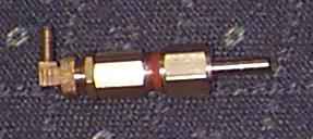
Then assemble the whole thing, and the finished product
looks like this.
The barb with the
orifice drilled in it (the 90^ barb) has to face the wastegate actuator,
and the un-drilled barb (the straight one) has to face the source of boost
(intake manifold or turbo output nipple)
To adjust the valve, unlock the
lock-nut, and screw the unit together, so that it gets shorter. The shorter you
make it, the higher the boost goes. You should be able to get it really close to
14 lbs without hitting cut out. Re-lock the lock ring, and it'll stay
where you set it.
The knurled knob turns to make
the valve body shorter or longer. The lock ring stops the movement after
adjustments are made. The vent orifice needs no filter, as it never sucks
air in. Making the valve longer LOWERS boost, while making the
valve shorter RAISES boost.
If you don't want to make your own,
DarrenDawes is
making and selling these controllers.
Here is a schematic from a factory T2 sticker that shows
one possibility of tapping into existing lines.
A late model T1 set up, like my 89's.
It has been noted that spiking seems to be minimal when
the lines are kept short, and the vent hole is kept small. Try .020" - .022" for
a vent hole.
HOME